Example 4: Mobile users and home users with VPN access
Illustration of a network managed by IBM® Sametime® Bandwidth Manager where mobile users and home users access a site using VPN Connections.
In this scenario, home users and mobile users establish VPN tunnels to an on-premise VPN concentrator across the internet. The VPN concentrator physically resides in Site A and is accessible from the internet through a bandwidth-constrained access link as shown in the following figure:
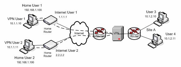
The home users have both a private IP address (192.168.1.100 for User 1) and a public IP address (1.1.1.1 for User 1). However, they also have a VPN IP address (10.1.1.10 for User 1). This VPN IP address is associated with the network adapter representing the VPN tunnel, and typically assigned by a DHCP server contacted by the VPN concentrator. For purposes of bandwidth management, only the VPN IP address is relevant.
Modeling this scenario contains two parts:
- Modeling the sites and links.
- Modeling the bandwidth constraints.
Modeling the sites and links
First model the sites and links by following these steps.
- Model the internet (representing home users and mobile users) as a site.
- Model the VPN concentrator as a site. Site A physically contains the VPN concentrator so in this model, it is labelled Site A.
- Model the link between the VPN concentrator (Site A) and the internet.
- Model a VPN site for home users and mobile users.
While home users and mobile users reside on the internet, they cannot actually be associated with the internet site, since the act of establishing a VPN connection typically disables direct internet connectivity. To represent connections from those users, use a separate VPN site instead of the Internet site.
- Because the VPN concentrator sits in Site A, model a connection between the VPN Site and Site A (the VPN concentrator).
Modeling the bandwidth constraints
After modeling the sites and links, model the bandwidth constraints.
- Model the bandwidth constraint for VPN connections.
Because of the tunneled nature of VPN connections, all VPN calls are routed through the VPN concentrator, even calls between two home users (in this example, VPN User 1 and VPN User 2). To correctly model the fact that calls between VPN users require bandwidth on the internet access link, the bandwidth constraint of that link must be associated with the VPN Site itself, rather than with the link between the VPN Site and the user's site.
- Model the VPN Site as requiring double bandwidth allocation for
calls.
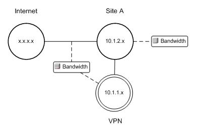
Calls between two different VPN users traverse the internet-VPN access link twice (once heading towards the VPN concentrator and then a second time back from it. This behavior means that the VPN Site needs to be modeled as a special type of site that requires double bandwidth allocation for calls. In the diagram for the model, the VPN site is shown using concentric circles to indicate its special nature.
- Make the link between the VPN Site and Site A have unlimited bandwidth.
The connection between the VPN Site and Site A does not need to be bandwidth-constrained because the VPN concentrator physically sits within Site A. Traffic within a physical site does not cause bottlenecks and does not require bandwidth management.
The topology model
The following figure shows the resulting topology model: