Example 1: Leased lines
Illustration of a leased-line network managed by IBM® Sametime® Bandwidth Manager. This example shows how you can model the simplest possible type of network, consisting of only two locations connected through leased lines.
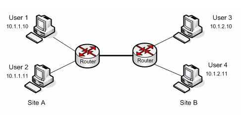
The following figure shows a simple network consisting of two locations connected through leased lines:
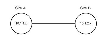
If you replace specific users and devices with sites and then connect the sites with links, the resulting network topology model looks like this:
At call setup time, the bandwidth manager figures out the route taken by the media through the modeled network topology, and allocates bandwidth as appropriate along the way. For example, for a call between an endpoint in Site A and an endpoint in Site B, different amounts of bandwidth can be allocated for Site A, for the link between the two sites, and for Site B. The amount of bandwidth allocated is determined by the settings configured for each of the sites and the link connecting them.