Creating an LPAR Profile
Using the PowerVM Create a logical partition (LPAR) Profile task, you can create an LPAR Profile for an existing LPAR from within the BigFix console.
Before you begin
You must activate the following analyses:
- PowerVM® HMC Overview
- PowerVM® LPAR Overview
- PowerVM® Managed System Overview
- PowerVM® VIOS Overview
For information about how to disable validation on certain parameters in the task, see Turning off validation in a task.
Procedure
- Open the Server Automation domain.
- From the Domain Panel, select , and select PowerVM Create a logical partition (LPAR) Profile.
- In the Partition section, add the
name, ID, and profile details of the new LPAR profile.
- HMC
- Select the Hardware Management Console on which the LPAR that you want to use is located.
- Managed System
- Select the PowerVM® managed system on which the LPAR that you want to use is located.
- Partition Name
- Select the LPAR on which you want to create a profile. To override the validation that is provided on the parameter, select OFF in the Validation column for the parameter. For more information, see Turning off validation in a task.
- Profile Name
- Enter the name of the new profile. To override the validation that is provided on the parameter, select OFF in the Validation column for the parameter. For more information, see Turning off validation in a task.
- From the Processing Mode list, select whether you want to add shared or dedicated processors to the new LPAR profile. If you select shared, the managed system assigns partial processor units from the shared processor pool to the new LPAR profile. If you select dedicated, the managed system reserves entire physical processors that can be used only by the new LPAR profile.
- In the Processing Settings section,
you can configure the processing settings for the new LPAR profile.
If you select shared from the Processing
Mode list, the task displays the following parameters: Minimum Processing Units, Desired Processing
Units, and Maximum Processing Units. If you select dedicated, the task removes
these parameters. Use the Total Processors available field to view how many processors are available on the managed system
that you selected.
- Minimum Processing Units
- Enter the minimum number of physical processors that you want to use to create virtual processors for the new LPAR profile. Each processing unit is equivalent to the processing power of one processor. You can enter whole numbers or decimal numbers. For example, 2 or 2.5 processor units can be assigned to the partition.
- Desired Processing Units
- Enter the number of physical processors that you want to use to create virtual processors for the new LPAR profile. Each processing unit is equivalent to the processing power of one processor. You can enter whole numbers or decimal numbers. For example, 2 or 2.5 processor units can be assigned to the partition.
- Maximum Processing Units
- Enter the maximum number of physical processors that you want to use to create virtual processors for the new LPAR profile. Each processing unit is equivalent to the processing power of one processor. You can enter whole numbers or decimal numbers. For example, 2 or 2.5 processor units can be assigned to the partition.
- Minimum Processing Units required
- View the minimum processing units to ensure that you enter valid values in the Minimum Processors field.
- Minimum Processors
- Enter the minimum number of processors that you want to assign to the new LPAR profile. Enter a value that is greater than the minimum processing unit.
- Desired Processors
- Enter the number of processors that you want to assign to the new LPAR profile.
- Maximum Processors
- Enter the maximum number of processors that you want to assign to the new LPAR profile.
- In the Memory Settings section,
enter the memory values for the new LPAR profile. Use the Installed Memory field and Current Memory
Available field to determine how much memory is available
to assign.
- Minimum Memory
- Select the minimum memory size that you want to set for the selected LPAR profile.
- Desired Memory
- Select the memory size that you want to set for the selected LPAR profile.
- Maximum Memory
- Select the maximum memory size that you want to set for the selected LPAR profile.
- In the General Virtual Adapter Settings section, enter the maximum virtual adapter values for the new LPAR.
- Maximum Virtual Adapters
- Enter the maximum number of virtual adapters that you want to connect to the new LPAR.
- In the Virtual Ethernet Settings section, enter values for the parameters in the Ethernet settings
of the new profile.
- Virtual Ethernet Adapter ID
- Enter the virtual Ethernet adapter ID. To override the validation that is provided on the parameter, select OFF in the Validation column for the parameter. For more information, see Turning off validation in a task.
- VLAN
- Enter the ID of the (Virtual Local Area Network) VLAN that you want to configure with the Ethernet adapter.
- In the Storage Settings section,
enter the storage values for the new LPAR. From the Storage
Type list, select whether you want Virtual Small Computer
System Interface (vSCSI) or Node Port ID Virtualization
(NPIV) storage for the new LPAR profile.
- If you select vSCSI, enter the
following parameters.
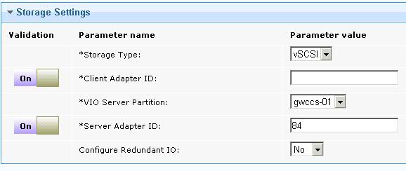
- Client Adapter ID
- Enter the ID of the LPAR client adapter that you want to use for the AIX® root disk of the new LPAR. To override the validation that is provided on the parameter, select OFF in the Validation column for the parameter. For more information, see Turning off validation in a task.
- VIO Server Partition
- Select the name of the virtual input/output server (VIOS) to which you want to add the adapter ID.
- Server Adapter ID
- Enter the adapter ID that you want to use on the VIOS for the root disk of the new LPAR. To override the validation that is provided on the parameter, select OFF in the Validation column for the parameter. For more information, see Turning off validation in a task.
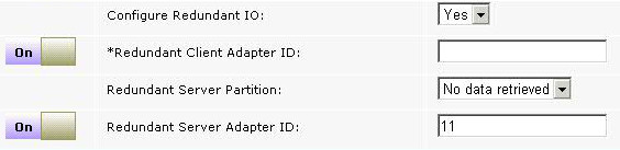
- Configure Redundant IO
- Select whether you want to configure an alternative path for multi-path input/output (MPIO) redundancy. If you select YES, you must enter the values for the following parameters: Redundant Client Adapter ID, Redundant Server Partition, and Redundant Server Adapter ID. The Hard Disk list is filtered and displays only hard disks that are configured for MPIO.
- Redundant Client Adapter ID
- Enter the ID of the redundant LPAR client adapter that you want to use for the root disk of the new LPAR.
- Redundant Server Partition
- Select the Redundant VIO Server that you want to configure to enable multi-path for the root disk of the new LPAR.
- Redundant Server Adapter ID
- Enter the redundant VIO server adapter ID that you want to use on the redundant VIO server for the root disk of the new LPAR.
- If you select NPIV, enter the
values for following parameters:
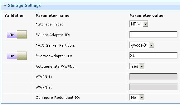
- Client Adapter ID
- Enter the ID of the LPAR client adapter that you want to use for the root disk of the new LPAR.
- VIO Server Partition
- Select the name of the (VIOS) to which you want to add the adapter for the root disk of the new LPAR.
- VIO Server Adapter ID
- Enter the adapter ID that you want to use on the VIOS for the root disk of the new LPAR.
- Autogenerate WWPNs
- Select whether you want to automatically generate worldwide port names (WWPN) for the client adapter. The default setting is Yes. If you select No, you must enter port name in the WWPN 1 and WWPN 2 fields. If you select No and you are configuring MPIO, you must also enter the Redundant WWPN 1 and Redundant WWPN 2 fields.
- WWPN 1
- Enter the first WWPN for the client adapter.
- WWPN 2
- Enter the second WWPN for the client adapter.
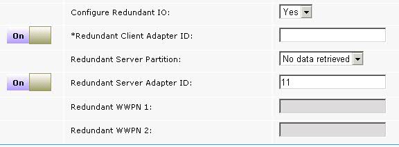
- Configure Redundant IO
- Select whether you want to configure an alternative path for multi-path input/output (MPIO) redundancy. If you select YES, the following parameters become visible: Redundant Client Adapter ID, Redundant Server Partition, Redundant Server Adapter ID, Redundant WWPN 1, Redundant WWPN 2.
- Redundant Client Adapter ID
- Enter the unique ID of the redundant LPAR client adapter that you want to use.
- Redundant Server Partition
- Select the name of the redundant server to which you want to add the redundant client adapter ID.
- Redundant Server Adapter ID
- Enter the redundant adapter ID of the Virtual I/O Server that you want to use.
- Redundant WWPN 1
- Enter the first redundant WWPN for the client adapter.
- Redundant WWPN 2
- Enter the second redundant WWPN for the client adapter.
- If you select vSCSI, enter the
following parameters.
- Click Take Action, and in the Take Action dialog box, target the LPAR on which you want to create a profile, and click OK.