System modeling
Introduction to a system model
A system model is a logical presentation of the components contained in a system under test and the relationships between components. You can create a system model when you want to visualize the different components and their relationships as a diagrammatic representation.
You can create only one system model within a team space on HCL OneTest™ Server. A team space repository is required to contain the system model that you create. Before you can create a system model, you must add a team space repository. The system model that is created or edited is stored in the team space repository. All projects within a team space share the same system model. All members of a team space can create, edit, and view the system model.
After you log in to HCL OneTest™ Server, you can go to the System Model page to create a system model for your team space. Alternatively, you can go to any of the projects in your team space and create a system model from the System Model page within a project. The system model is accessible from all the projects in your team space.
Components in a system model
Components are the basic building blocks that are used to represent a piece of software in an application.
| Component type | Description |
|---|---|
| Database | The component type represents the database resource. You can select this component type when you want to represent a database asset or resource in the system model. |
| Service | The component type represents the virtual service resource. You can select this component type in the system model to represent a virtual service in the team space repository or associate a virtual service resource that is in the project repository. |
| UI | The component type represents the user interface (UI) resource. You can select this component type when you want to represent the UI resource in the system model. |
Component relationships
You can create multiple components to depict the different resources in the system or application under test. You can create a component as a child component of a parent component. You can also create multiple components as children components of the same parent component.
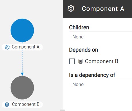
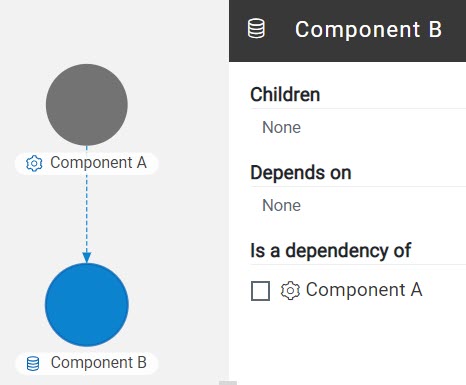
You can define the relationship between components if one component depends on another or if a component has a dependency of another component. The Depends on or Is a dependency of relationship depends on the component that you select in the system model after you define the relation.
For example, if you define Component A to depends on Component B, then the relationship is displayed with a line arrow from Component A to Component B, and the arrow points to Component B.
Component associations
When you work with the system model from your project in a team space, you can associate test resources that are in your project repository with components in the system model. You can associate all types of test resources such as Suites or tests, and virtual service resources with the components.
After associating test resources, you can view them when you select the component with which they are associated. You can select the associated test resources to start a run of the Suites or tests or start an instance of the virtual services resource.
Using the system model UI
| Icon | Description |
|---|---|
| Represents a system model. | |
| Represents Suites and tests in a repository. | |
| Represents a database resource. The component name is prefixed with this icon when you select the component type as database. | |
| Represents a service resource. The component name is prefixed with this icon when you select the component type as service. | |
| Represents a user interface (UI) resource. The component name is prefixed with this icon when you select the component type as UI. | |
| Represents the virtual services. | |
| Represents the dependency between the components. | |
 |
Represents the inherited dependencies. |
| Icon | Used for... |
|---|---|
| Adding components, child components, or dependent components. | |
| Searching for components in the system model. | |
| Publishing the changes made to the system model, changes made to components, or changes made to component associations. The changes are published to the team space repository. |
| Operation | Action |
|---|---|
| Pan the view of the model |
|
| Zoom in the view of the model |
|
| Zoom out the view of the model |
|
| Reset the view |
|
| Position the model view |
|
Tasks in system modeling
When you want to model the system under test for the first time after you install the server software, you must first add the team space repository. See Adding a repository to a team space.
After a repository is configured as the team space repository, you can work with the system model. See Tasks for working with a system model.
When you want to change, update or delete the repository, you can work with the team space repository. See Tasks for working with the team space repository.